
Posted by Jason Lillywhite
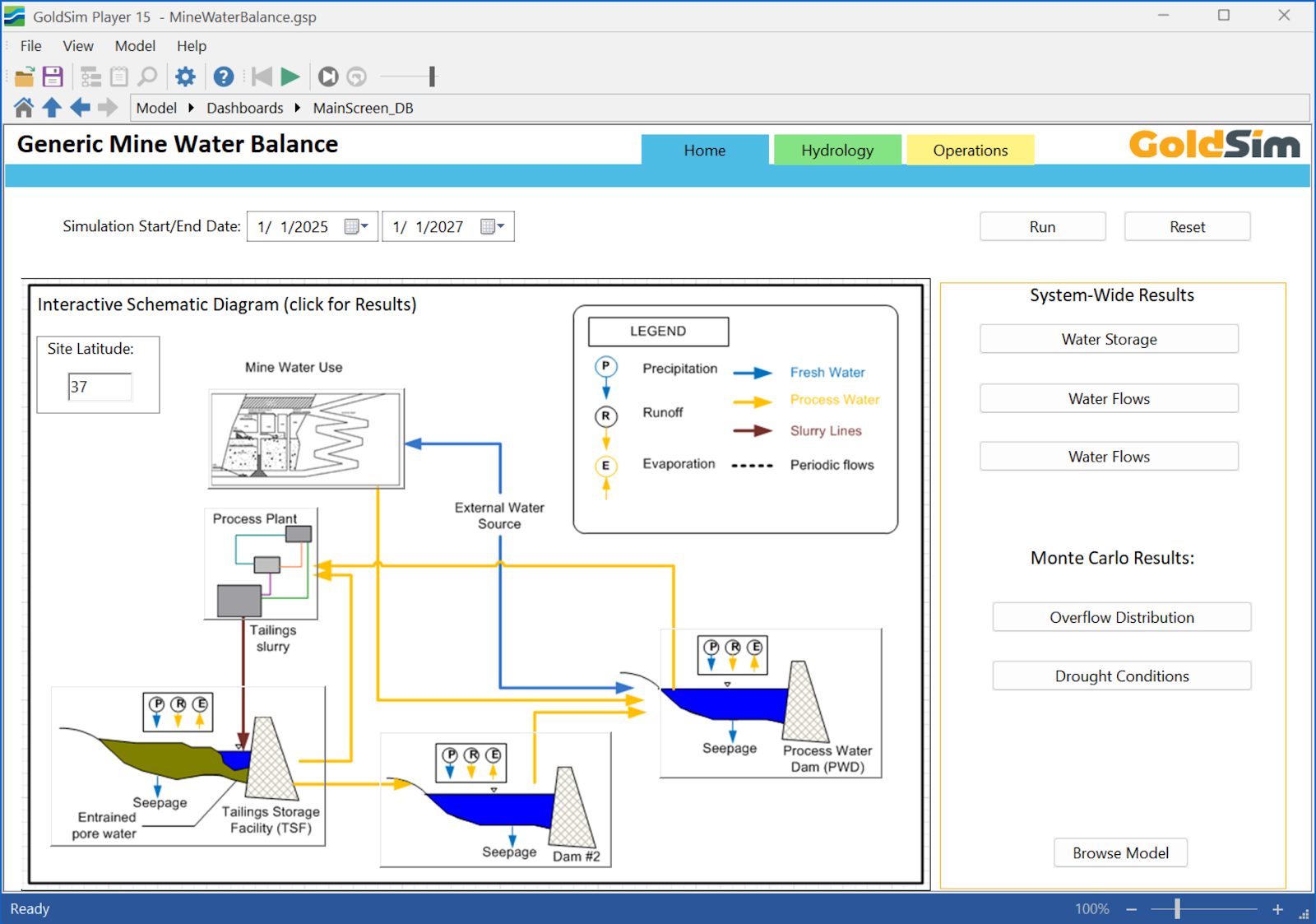
Our conceptual Mine Water Balance model, built in GoldSim, has been updated to take advantage of the latest software features and align it with to our own Style Recommendations. This model, designed as an educational template rather than a site-specific solution, demonstrates the interconnectedness of key facilities such as a Process Water Dam (PWD), a secondary buffer dam (Dam 2), a Tailings Storage Facility (TSF), and the Process Plant.
 |
| A glimpse into the simulated mine water system. |
Mass Balance Test
 |
| System-Wide Mass Balance Test |
 |
| All Mass Balance Tests |
Updated Dashboards
 |
| Home Dashboard |
Navigating to the Hydrology tab brings you to a dashboard for managing hydrological inputs. This interface provides input controls for setting up climate parameters, defining evapotranspiration (ET) losses from water surfaces and land, and configuring catchment runoff characteristics that contribute to the system.
 |
| Hydrology Dashboard |
 |
| Operations Dashboard |
Dynamic Flow Control with Controller Elements
This model uses GoldSim's Controller element to dynamically manage flows at multiple locations within the water system. Some flows in the system are not controlled using feedback. But other flows are controlled based on the state of a model variable, like water level or volume in a pond. These controlled flows can be simulated in a straighforward way using the new GoldSim Controller elements. This element controls flow rate based on comparing a Process Variable (the PWD volume in the example shown below) to a defined operating target.

The PWD_Pump_Controller (shown above) adjusts the pump supply to the Process Water Dam by comparing the current PWD volume against its set target volume. Applying this controller logic at various points allows the model to simulate more realistic operational adjustments to flows based on system conditions, rather than relying on predefined or fixed flow rates.
 |
| Time History of PWD and Operating Target with Outflow |
Model Organization
The GoldSim Mine Water Balance model uses a hierarchical structure with a modular approach. The root level provides a direct overview and access to all primary functional areas, organized around the core System Model container. This central hub contains the detailed logic and calculations representing the mine water system, including its dams, TSF, and process plant interactions.
 |
| Root Level of the Model |
The Input_Data container organizes all primary data, parameters, and time series that drive the simulation. Model outputs are collected, processed, and displayed within the Results container, often using charts and tables. The Dashboards container offers customized interfaces for visualizing key results and controlling model runs. Linked with the System Model, the Information_References container contains references to model states that are fed back into the System_Model. This is known as feedback, which is commonly used to control flows between system components (like Dam 2 to PWD). Finally, the Testing container is dedicated to mass balance accounting.
System Model
The core of the Mine Water Balance simulation is represented within the System Model, which dynamically tracks water movement between operational areas. The primary components and their interactions, as illustrated in the diagram, are as follows:
- System Model: This is the overall system flow network. Flows not shown here are system losses and gains like precipitation and evaporation.
 |
| Mine Water System Model View |
- Mine: The Mine generates Mine Discharge water, which is directed to the Process Water Dam.
- Process Water Dam (PWD): The PWD acts as a primary collection and distribution point for water within the system. It receives Mine Discharge from the Mine and, also receives regulated flow from Dam 2. The PWD then provides Plant Supply water to the Process Plant. The operating goals are to supply process supply water and prevent overflows to the environment.

Process Plant: This unit consumes water for mineral processing, receiving Plant Supply from the PWD. After use, the Process Plant discharges Slurry to the Tailings Storage Facility. It also receives Reclaim water back from the Tailings facility. Since reclaim causes a recycle flow in the system, we use a Material Delay to break the recursive loop.

- Tailings (Tailings Storage Facility - TSF): The TSF receives Slurry from the Process Plant. Reclaim water is actively pumped back to the Process Plant for reuse. Any excess water that is not reclaimed or stored within the TSF is discharged as TSF Overflow to Dam 2.

- Dam 2: This facility serves as buffer storage. It captures TSF Overflow from the Tailings facility. Dam 2 then plays a crucial role in recycling water within the system by regulating and sending flow back to the Process Water Dam (PWD), thereby completing the flow loop.

This interconnected system allows the model to simulate how water is sourced, used, stored, and recycled throughout the mining and processing operations, highlighting the interdependencies between each component.
Model Documentation
 |
| Side-docked Note Pane |
 |
| Bottom-docked Note Pane |
Conclusion
This update to the conceptual Mine Water Balance model integrates several enhancements designed to support a clear understanding of complex mine water management. The changes encompass a reorganized model structure for improved visualization, robust mass balance tests for validation, the implementation of dynamic flow controls using GoldSim's Controller elements, and updated dashboards.
You can download the model as a Player file or the actual GoldSim model from our library here: Mine Water Balance – GoldSim Help Center.
No comments:
Post a Comment